Review on steel bucket spot weld welding control technology
Text / Bao Lili
[Editor's note] This paper introduces various thermal cycles and pressure cycles and their applicable range in the production of steel barrel spot welding and seam welding processes; details the high-precision network voltage compensation control constant current control technology, as well as the correct selection and use. Some problems with various controllers.
Spot welding and seam welding are the main processes in the production of steel drums. They are internationally accepted in the process of seam welding and barrel spot welding of steel drums, so they are the most widely used.
Factors affecting the quality of spot welding and seam welding are manifold, such as materials, processes, and tooling. However, under normal production conditions, materials, processes, and tooling are not determined to change frequently. Therefore, the main reason affecting the quality of welding is the fluctuation of the welding process parameters. In order to ensure good welding quality, it is necessary to understand and study the control techniques of spot welding and seam welding.
1. Control objects for spot welding and seam welding
1. Three elements of spot welding and seam welding control
The current, electrode pressure and energization or pressurization time and electrode diameter (for the thickness of the seam welding roller) during spot welding and seam welding are the main process parameters affecting the welding quality. The diameter of the electrode increases as the number of solder joints increases, which is foreseeable and is always in the operator's view. Therefore, the current I, the pressure P, and the time t constitute the three elements of the spot welding control.
The combination of these three elements produces various thermal and force cycles for the spot and seam welding processes. The brief introduction is as follows:
The basic cycle (Figure 1) consists of four steps of preloading, welding, maintenance and rest. Current is passed only during the welding step. The nominal pressure of the electrode of the basic cycle is constant, and the dotted line portion of the pressure curve in the figure indicates that the pressure is increased at the end of the welding for forging, which is no longer a basic force cycle. The basic cycle is used for the welding of general structures.
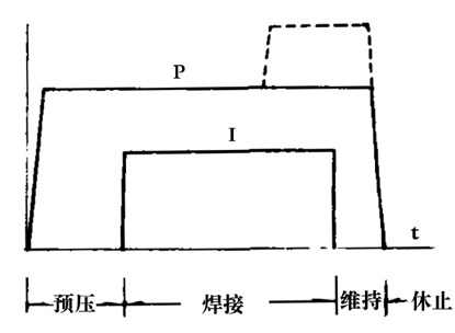
Figure 1 Basic cycle
Multi-pulse cycle: The welding step in the basic cycle uses the pulse energization mode to be a multi-pulse cycle. The most common is the double pulse cycle, also known as the secondary pulse cycle. This type of circulation is mostly used for spot welding and projection welding of steel drum sealers.
Thermal cycle with preheating and tempering current pulses: This cycle has eight steps, which are to increase the preheating, cooling and cooling, and tempering steps before and after the basic cycle of the welding step (Figure 2). In the preheating, welding and tempering steps, current flows through. In general, the currents in these three steps are different in magnitude, and the welding step itself can be energized by multiple pulses. The cycle with preheating and tempering current pulses is mostly used for medium carbon steel, alloy structural steel and other heat treatable materials, and is also commonly used for the welding of steel barrel sealers.
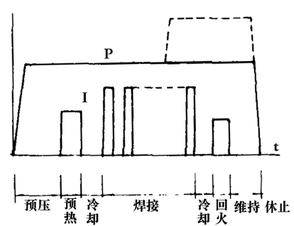
Figure 2 Thermal cycle with preheating and tempering pulses
The thermal cycle of the current ramping down: the switching of the current in the welding step of this cycle has a gradual feature. The slow rise and fall are generally linear, and there are also exponential curves (Fig. 3). Of course, it can be controlled to use only the slow rise section instead of the slowdown section. This thermal cycle is mostly used for the welding of coated steel sheets and the welding of hot rolled pickled steel sheets.
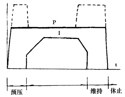
Figure 3 current slow rise and fall thermal cycle
The cycle of force can be classified as:
(1) The pressure does not change. The electrode pressure from pre-compression to maintenance step is always the same.
(2) Pressure change cycle. Generally, it can be divided into two types: increasing pressure mode and "saddle" type, as shown in Figure 1 and Figure 3.
Sew cycle (Fig. 4): The seam welding process can be seen as a process of continuous spot welding of overlapping solder joints. Its thermal cycle is similar to the basic cycle of force cycling and spot welding.
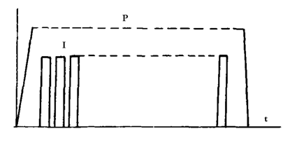
Figure 4 seam welding cycle
2. Control accuracy of three elements of welding
Current I: According to Joule-Lenz's law, current I is the most important factor affecting spot welding and seam welding. The current used for spot welding and seam welding in steel drum production is generally 10 to 15 kA. The main interference factors affecting the accuracy of current control are network voltage fluctuations; changes in the inductive reactance of the welding circuit; changes in the thickness and number of layers of the welded sheet and the shunting of the welded joints. The control requirements for the welding current can ensure the stability of the welding current in the presence of many disturbances above, and the rate of change does not exceed 5%; not exceeding 3% is a higher requirement, and is also a common requirement in the production of steel drums. For a single interference factor, the change of welding current should be no more than 2%, which is also a good level of foreign welding control.
Time t: The time of each step of spot welding is generally in units of cycles. The frequency of China's power grid is 50 cycles. The fluctuation of time comes from changes in timing circuit parameters, fluctuations in network voltage, and the like. If the counting circuit is used, the error can be zero with the grid cycle timing. The general allowable time error in steel drum welding is 10%, and the time error of important parts should be zero.
Pressure P: Pressure P is the force of the welding mechanism of the welding device. The force applied to the weld by the cylinder, cylinder or lever is expressed in KN (kN). The fluctuation of the pressure comes from fluctuations in the pressure source (compressed air, pressure oil, etc.) and changes in the friction of the pressurizing mechanism. For pressure changes, it should generally be limited to 10%, and the higher requirement is 5% or less.
3. Relationship between three elements and welding performance
The relationship between the three elements of current, time and pressure and the weldability of the material can be represented by the weldability map. Fig. 5 is an example of a spot welding performance map of a low carbon steel cold rolled sheet. As can be seen from the figure, the different combinations of current and energization time result in three regions. Above is the welding splash zone, which has poor welding performance. The middle diagonal line part is the qualified solder joint area, and the welding performance is good, and the production specification can be selected in this section. We recommend the “▲†part as the specification for production. The wider the diagonal line interval, the better the welding performance of the material. Below is the area of ​​insufficient solder heat, which has insufficient strength.
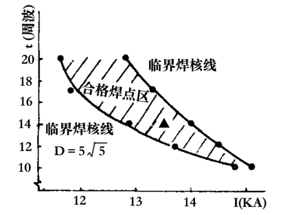
Figure 5 Welding performance of low carbon steel cold rolled steel sheet
As the electrode pressure increases, the oblique line in the figure will shift to the right, the electrode pressure will decrease to the left, and the width of the oblique line will also change slightly, and its shape will be substantially maintained.
If the pressure and time or current and pressure are used as the coordinate axes, another form of welding performance map can be obtained, which is not analyzed here.
Second, the general composition of spot welding, seam welding controller
Figure 6 shows the general composition of spot welding control. The external appearance of the parameter presets in the figure is the panel of the controller through which the parameters of the current (or heat) and pressure changes are placed for all steps. The number can be set by knob or digital (numeric keys or numeric dial). In the figure, the current feedback and voltage compensation links are all indicated by dashed lines. In general, there is usually only one of them in the general controller. Only the high-performance controller can have these two functions at the same time, so that the user can choose it in actual use. The pressurizing mechanism is generally a cylinder or a cylinder and its transmission. Current control is achieved by adjusting the conduction angle of the welding main current thyristor.
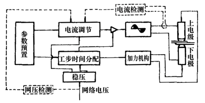
Figure 6 General composition of the spot welding controller
Third, voltage compensation type spot welding, seam welding controller
1. Analog voltage compensation controller
This kind of controller is the most widely used in China. The voltage compensation condition is that the change of the welding current is not more than 5% when the network voltage changes by 10%. The time control accuracy can be zero. But they don't have linear thermal control. Its ability to control various thermal and force cycles varies by model.
2, digital voltage compensation spot welding controller
This is a high-precision spot welding controller whose voltage compensation accuracy can reach 20% of the network pressure change, and the welding current does not change by more than 2 to 3%. Foreign high-performance controllers can reach 2% level. This type of product is already available in China.
To achieve high-precision voltage compensation must be based on linear thermal control, it is necessary to use microcomputer control technology.
Heat is a term used in spot welding control technology, unlike the concept of heat in physics.
When the thyristor in the main circuit of the welding is fully turned on, the current is 100, and the ratio of the effective value of the current corresponding to a certain conduction angle to the effective value of the current during the full conduction is called the heat during spot welding. Therefore, heat is a function of the thyristor, also known as the heat function (Fig. 7), which in turn takes the power factor angle of the welding loop as a parameter variable. Linear thermal control precisely controls the heat in percent, and there is a linear relationship between the given heat and the actual welding current.
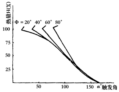
Figure 7 heat function
To achieve accurate digital compensation of network voltage changes, a set of heat functions with multiple power factor angles as parameters are stored in a micro-machine spot welding controller in the form of data sheets. When the welding is performed, each cycle (or half cycle) should detect the network voltage. If the network pressure changes to a negative direction (such as -10%), the controller automatically reduces the firing angle to increase the heat by 10% to ensure the actual welding current. The value does not change.
Fourth, constant current type spot welding, seam welding controller
The constant current spot welding controller not only solves the most common network pressure fluctuation problem in general factories, but also solves the problem that the inductive reactance of the long arm welding circuit in the steel barrel welding is large and affects the welding quality. However, the constant current cannot solve the problem that the shunt affects the quality due to the close proximity of the solder joints.
In the early years, the constant current type spot welding controller used to use analog electronic circuits, and its effect was not satisfactory. Today's constant current controllers basically use microcomputer control technology, and also use linear thermal control technology (see Figure 6). The operator presets the welding current from the welding parameters, and the effective value of the welding current is detected on the cycle by cycle (or half a year). The feedback is fed back to the heart of the controller, which is automatically generated by the microprocessor according to the heat function of the memory. Adjust the firing angle α of the next cycle (or half cycle) so that the current expected next cycle (or half cycle) of the current tends to a given value.
For reference, Figure 8 shows a block diagram of a constant current spot welding and seam welding controller. The current sensor 1 (Rogowski line diagram) detects the differential signal of the welding current, and sends it to the microprocessor 4 via the integrator 2 and the analog-to-digital converter 3 for sampling and calculation to obtain an actual current effective value. The required constant current value is set by the keyboard 5 and stored in the random access memory 8, and the current control curve is stored in the read only memory 7. The microprocessor calculates the thyristor firing angle of the next striking wave according to the current firing angle and the difference between the side current and the given current, and outputs it through the timer 9 and the trigger circuit 10. 11 is a current zero pulse generator and 12 is a pulse discriminator. This constant current controller generally stabilizes the current within 3%.
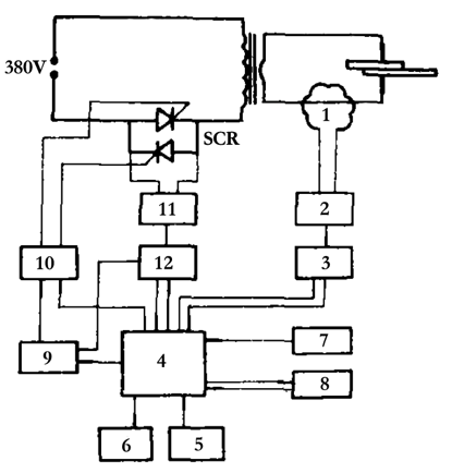
Figure 8 Constant current point seam welding controller block diagram
Five, solder joint (seam) physical state monitoring technology
Control point (slot) welding process parameters have been introduced to ensure welding quality, which is effective in many occasions. However, it is neither the only method nor the ability to overcome all kinds of interference factors that affect quality.
In this case, the physical state monitoring technology of the solder joint has been developed. The so-called physical state monitoring means that the solder joints are accompanied by regular changes in some physical quantities during the growth process to control the welding quality. The relationship between the state of this physical quantity and the quality of spot welding is often more tight and more intrinsically linked than the process parameters. The electric quantity, temperature, thermal expansion amount, etc. of the solder joint can be such a physical quantity. Here are two ways to do this:
1, dynamic resistance monitoring technology
The so-called dynamic resistance refers to the resistance of the weld zone between workpieces during spot welding, because it changes with the process of welding energization, so it is called dynamic resistance. This monitoring technique is a method that uses the law of dynamic resistance change during spot welding to control certain characteristic values ​​on the resistance change curve or follow a preset typical curve to control the quality of the solder joint. This method has good adaptability to materials such as low carbon steel, stainless steel and low alloy steel. It has been applied abroad, and the effect is very good. Because the monitoring technology is more complicated, it has not been widely used in China.
2. Thermal expansion monitoring technology
During the spot welding process, the metal expands due to heat, especially when the metal melts into a liquid state. The molten metal is surrounded by cold metal. In the direction of the electrode axis, although the electrode pressure exists, since the cold metal is very thin, the liquid metal can only expand in this direction, so-called electrode displacement. The amount of electrode displacement reflects the size of the weld nugget. This monitoring method is also known as electrode displacement monitoring. The main monitoring parameters are initial displacement velocity (ds/dt) and maximum displacement (Sm). These two parameters can be jointly monitored, or only Sm can be monitored. This method requires the rigidity of the welder to be good and the accuracy of the displacement sensor to be high. This technology is currently not widely used in domestic steel drum production.
Six, a few special issues
1, the first half wave firing angle
The specification of many spot welding controllers at home and abroad stipulates that the first half-wave firing angle of current conduction is 85-89°, and the conduction angle (heat) of the first half-wave is fixed and cannot be adjusted, and then each cycle The heat is adjustable. The general explanation is that setting the first half-wave firing angle to 85-89° is beneficial to quickly establish the magnetic flux of the welding transformer and reduce the inrush current during the transition process. This is particularly advantageous for transformers in which high permeability silicon steel sheets are wound around the core.
2. Power factor adaptation
It can be seen from the foregoing Fig. 7 that the relationship between the heat H and the firing angle Φ is greatly affected by the welding circuit power factor (Φ angle). The power factor angles of different welders vary widely. The fixed spot welder has a Φ angle of about 45-65° depending on the length of the arm, and the Φ angle of the suspended spot welder is about 55-65°. The secondary rectification spot welder has a Φ angle of about 20 to 30°, and the position of the workpiece in the arm or jaw can also affect the Φ angle by 4 to 5°. Therefore, many spot welding controllers have developed power factor adaptation. Without this function, the heat control is extremely inaccurate, and it is prone to serious accidents such as single tube conduction and burnout of the thyristor, and it cannot fully utilize the capacity of the welder. Therefore, when choosing a welding controller model, you should pay full attention to whether it has power factor adaptive function.
The grill rack chicken leg wrings great for Use in the Oven, Smoker, or on the Grill. Multi-Purpose 12 Slot Leg and Wing Rack for Poultry. Excellent way to cook Chicken Legs and Wings to Perfection. Check food for doneness. Serve and Enjoy. The large grill rack is perfect size for cooling cookies, pies, and cakes, baking dishes and pans, steaming vegetables, and more.BBQ fish meat net barbecue grill mesh wire clamp outdoor stock the food on the net for turning over at ease.
Bbq Grill Rack,Grill Rack,Barbecue Grill Rack,Round Grill Grates
MEO DEMO CO., LTD. , https://www.meokitchentools.com