Discussion on automatic feeding device of stamping and its feeding precision
Text / Sun Ziwei
I. Overview
In recent years, China's steel drums and supporting enterprises have introduced many high-speed precision presses, multi-station presses and CNC die turntable presses. Each barrel equipment manufacturer is also accelerating the development of new and efficient. The high-precision and high-level stamping automatic production line has made China's steel drum stamping production a big step toward technology-intensive.
High-precision, high-speed stamping production lines are usually complete processing systems with unwinding, automatic feeding, and waste disposal. In order to provide complete sets of automation equipment, the barrel manufacturing equipment must develop various types of attachments, and affiliated The device is centered on an automatic feeder.
For the constant speed press, when a pair of molds are used for blanking or punching, the ordinary feeding device can meet the product precision requirements; and for the high-precision, high-speed press, the feeding device using the ordinary structure obviously cannot satisfy the product. The accuracy requirements. The precision of the machine tool is high, the feeding accuracy is not up, and the stamped parts produced are still waste products. Therefore, the feeding device and the accuracy problem are an important research topic at present. This paper analyzes various factors affecting the accuracy of feeding, and from the years of production practice and teaching research experience, discusses the measures to improve the feeding accuracy.
Second, factors affecting the accuracy of feeding
As described above, for a normal speed press with a stroke number of 200 beats/min or less, a normal roller type feed device can be used; but for a high speed and high precision press having a stroke number of 100 to 2000 times/min, a feed device is required. It is also high-speed. When the feeding speed reaches 30m/min and the feeding pitch is more than 200mm, the feeding accuracy can not be met by the ordinary feeding device. To develop a high-precision feeding mechanism, you must first understand the factors that affect the accuracy of feeding.
The feeding accuracy is related to the equipment, manufacturing, production process, and stamping material of the feeding device.
(1) Design. Including the choice of institutional plan, the rationality of structural design, design calculation error, miscalculation calculation error, length of transmission chain, etc.
(2) Manufacturing. There are machining errors, assembly errors, and transmission mechanism clearance values;
(3) Process. Feeding speed, feed stability, part shape change, part failure;
(4) Uniformity of material thickness, surface smoothness, etc.
Although the factors affecting the accuracy of feeding are manifold, the accuracy of one feeding is most dependent on the feeding speed. The average feeding speed of the feeding device is the product of the feeding distance and the number of feedings per minute. During the working period of the press, the feeding time is usually only 180° crank angle, and the feeding speed is not constant during the feeding process, the actual maximum feeding speed. About three times the average speed, increasing the feed speed will reduce the feeding accuracy, which is contrary to the way to improve the feeding accuracy, so other ways should be studied.
Third, measures to improve the accuracy of feeding
In the automatic stamping production of strips or coils, the feeding devices used are mainly roller type, clamp type, clamp type, hook type and the like. Among them, the roller type has a dominant position, so the roller type is taken as an example to discuss, and the principle has the same meaning for other types of feeding devices.
Figure 1 is a schematic view of a roller feeder. The roller shafts 1 and 2 are fixed on the press table, driven by the eccentric wheel 8, the connecting rod 7 and the single clutch 5, etc., the roller shaft rotates periodically, the strips are fed intermittently, and the upper roller shaft 1 is rotated. In addition, it can also move vertically, pressing the spring 6 against the lower roller shaft, and the roller shaft clamping material 3 is fed forward due to the frictional force between the roller shaft and the material. According to the working principle analysis, in order to improve the feeding accuracy, the method can be adopted: due to the friction between the roller shaft and the material, the roller shaft is fed, so the relative sliding between the feeding roller and the material should be prevented; Accelerate transportation, stop suddenly when it terminates, so it is necessary to prevent the acceleration shock at the start and end of feeding and the accurate positioning of the end of the stroke.
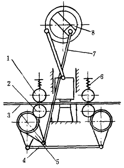
Figure 1 Working principle of the roller shaft feeding device
1-upper roller shaft; 2-lower roller shaft; 3-grip material; 4-linkage;
5-clutch; 6-spring; 7-link; 8-eccentric
1. Prevent relative sliding between the feed roller and the material
In order to prevent relative sliding between the feed roller and the material, the contact pressure of the roller to the material can be appropriately increased, and the pressure can be determined by the following formula during design:
![]()
Σy - allowable contact pressure, Pa
P——the total pressure of the roller on the material, N
E - the modulus of elasticity of the material, Pa
R——roller radius, cm
L——material width, cm
Generally, σy=0.5σB is taken.
The pressure can be adjusted by adjusting the compression spring or increasing the shaft diameter from the structure. However, in order to prevent the increase of the moment of inertia, do not excessively increase the shaft diameter. Generally, R>15h (h is the material thickness).
In addition, it is also possible to knurl and mill grooves on the surface of the roller shaft to improve the friction coefficient between the roller shaft and the material to prevent sliding between the rollers and the material.
2, the end of the stroke is accurately positioned
(1) Reduce the transmission inertia at the time of feeding. The high-speed feed roller can be made into a hollow structure; the roller shaft is made of light metal; the one-way clutch uses a small-shaped profiled roller friction clutch.
(2) Install reliable and perfect brakes. Designed to consider the brakes that overcome the inertia of the feed; reduce the adjustable pressure device for sliding; prevent the reverse brake from overrunning the clutch.
(3) A positioning pin is mounted on the mold to control the final position of the strip. Although this is a small measure, it tends to have a significant effect. For a multi-station press designed for a factory, the roller feed accuracy required by the user is ±0.05mm. Because the previous stamping products, hundreds of thousands a day, if the feeding error is dozens of wires, a few hundred meters of steel sheet is wasted in one day, and various measures are not effective for this. The newly designed multi-station punching machine utilizes the position of the blanking hole after punching and is positioned by the positioning pin synchronized with the slider to ensure the accuracy of the blanking hole pitch.
3, to prevent the start of feeding and accelerate the impact at the end
The prevention of acceleration shock at the beginning and end of feeding is mainly considered from selecting a suitable feeding mechanism.
At the beginning and end of the feed, the material undergoes a sudden increase in acceleration, which inevitably produces shock and vibration. In the case of high-speed feeding, the shock and vibration sharpening brushes are increased, and the feeding accuracy is also drastically lowered. Therefore, for high-speed feeding (v>30m/min), a one-way friction clutch is not used, and the following smooth moving stepping mechanisms are employed.
(1) Arc cam stepping mechanism
As shown in Fig. 2, the circular arc cam 1 is like a spherical worm with a helix angle, so it is also called a worm cam mechanism, and is called a Fukaisen mechanism abroad. A plurality of cylindrical rollers 3 are uniformly distributed in the circumferential direction of the follower rolling 2, and the number of rollers is generally 6 to 8. The cross section of the working surface of the cam is trapezoidal, which is kept in contact with the roller, and the worm cam rotates at a constant speed, and the follower generates intermittent motion. For a single-head worm cam mechanism, the cam turns one turn and turns from the action to a roller pitch.
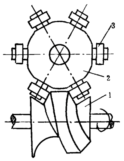
Figure 2 Arc cam stepping mechanism
1-cam; 2-roller; 3-roller
Worm cams are generally designed with a sinusoidal motion law, designed to change the maximum speed of motion. During operation, the mechanism can ensure that the two working surfaces of the cam work surface are in close contact with the two rollers, and the gap is eliminated. When the spiral angle of the transition reaches zero, the follower stops immediately, and the inertia is small, so the impact vibration is greatly reduced, and Precise positioning is achieved without the use of a brake. At present, when the mechanism is intermittently indexed, the number of strokes of the press has reached 3,000 times/min, which is suitable for feeding on high-speed, high-precision automatic presses. The 60-ton high-speed automatic press developed by Münster Company of the United States has a maximum stroke of 1600 beats/min. It adopts the roller feeder of Fukaisen mechanism to feed at a speed of 120m/min with an accuracy of ±0.025mm.
(2) Cylindrical cam type stepping mechanism
As shown in Fig. 3, the surface of the cylindrical cam 1 has two convex and contoured profiles, the driven member is a circular disk, and the end faces thereof are uniformly distributed on the circumference of the radius R1 by a roller A, B, C. .... The drive shaft 4 and the driven shaft 3 are vertically staggered, and the cam contour from R1 is just between the two rollers. When the cam rotates in the direction shown, the roller B on the disc begins to enter the curved section of the contour, the cam The rotation drives the follower 2 to rotate, and the roller A is disengaged from the contour. When the cam rotates through 180°, the follower rotation ends, the contour line in contact with B begins to transition from the curve to the straight line, and the C roller adjacent to the B roll starts to contact the other side of the line, and the cam continues to rotate. The disc does not move to achieve an interval. Intermittent stages B and C are simultaneously attached to both sides of the straight contour to lock the positioning of the driven disc.
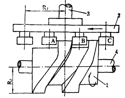
Figure 3 cylindrical cam stepping mechanism
1-cylindrical cam; 2-disc; 3-driven shaft; 4-actuating shaft
To ensure intermittent positioning, the cam linear profile width b should be the shortest distance between the adjacent two roller surfaces (Figure 4).
![]()
Where R1 - the center of the roller on the disc to the center of the disc
Α——half the step angle, α=π/2
D——roller diameter
z - the number of rollers, usually z> 6 ~ 8
When the shape of the cam curve is properly designed, the follower can obtain ideal motion conditions, such as small dynamic load, no rigidity and flexible impact, and high precision. It is also suitable for high speed, light duty presses and has been successfully used for stepping operations of 1500 strokes per minute.
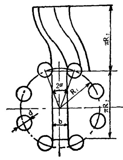
Figure 4: Dimensional drawing of the cylindrical cam stepping mechanism
(3) Planetary wheel stepping mechanism
It is fed by the reciprocating motion of the trajectory of the point on the eccentric mechanism of the planetary gear. When the planetary gear 2 shown in Fig. 5 is rotated around the center wheel 1 which is rounded, each point on the circle is drawn into a trajectory belonging to a cycloid type. The point on the circumference draws the cycloid 4, and the other points also draw different metamorphic cycloids. If the center wheel diameter is D and the planetary wheel diameter is d = 0.5D, then these cycloids are two-leaf cycloidal lines. A point E on the planet wheel in the cycloid, when EO1:d:D=1:5:10 is met, the pendulum drawn by point E is as shown by curve 5, which has an approximate straight line at each end in the x direction. When the slider 6 is driven by the E point, the slider reciprocates in the x direction and has an intermittent pause time at both ends.
This mechanism can be used for gripper feeding devices with a large feed distance and a medium speed. It runs smoothly, the acceleration curve is close to the sinusoidal curve, and the impact is small. As long as the parameters are reasonably selected during design, the wave convexity can be calculated to obtain better feeding accuracy.
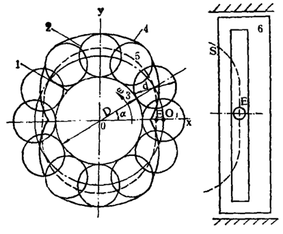
Figure 5 Schematic diagram of the planetary wheel half stepping mechanism
1-center wheel; 2-planetary wheel; 3-planetary wheel and center wheel point;
4-cycloid; 5-way pendulum drawn by point E; 6-drive slider
(4) Cam indexing star wheel roller shaft feeding mechanism
China's self-designed and manufactured 100-ton high-speed press, which consists of complete automatic lines with unwinding leveling, automatic feeding, and waste disposal. The feeding device adopts the cam indexing planetary roller shaft type (see Fig. 6), and uses a pair of hanging wheels (speed ratio 1/3 to 3) to form nearly 100 series with a step difference of 0.5 to 3.5 mm, forming the main feeding distance S. In part S1, a mandrel S2 wheel is fed into the feed roller by a planetary mechanism through a cone-rolling continuously variable transmission, so that S=S1+S2 and form a completely continuous sequence. The feeding accuracy is mainly determined by the gear precision. The cam adopts a sinusoidal curve, so that the acceleration of the feeding start and end points is zero. When the maximum number of strokes is 700 beats/min and the feed speed reaches 50m/min, the feeding accuracy can reach ±0.05mm.
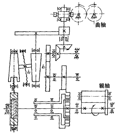
Figure 6 Schematic diagram of the cam indexing star-row roller shaft feeding device
4, the problem of the transmission chain
The driving method of the feeding device is various, but in order to ensure the synchronization of the feeding and the working of the press, the movement of the feeding device is generally transmitted by means of the crankshaft or the slider. The commonly used transmission mechanism is:
(1) The crankshaft end lever is used to drive the connecting rod to form a crank rocker mechanism, so that the one-way clutch is moved and the pull rod of the material roller is directly driven;
(2) The eccentric wheel drives a rack gear, so that the one-way mechanism swings and drives the rack-and-pinion type of the feed roller;
(3) The eccentric wheel transmits the movement to the pull rod of the one-way mechanism through the tie rod and the equal arm lever-lever type;
(4) The slider is equipped with a wedge to push the rack gear, and then through the sprocket, chain and gear mechanism wedge-gear type;
(5) a cam lever type that is mounted on the crankshaft end face cam by a lever mechanism;
(6) Others include the Malization Mechanism, the Electromagnetic Clutching Mechanism, and the hydraulic transmission and pneumatics.
The choice of transmission mechanism has a certain influence on the feeding accuracy. If the above transmission mode is called direct drive or indirect drive, we should try to choose direct drive to avoid the transmission chain is too long.
Practice has proved that direct drive is more accurate than indirect drive feed. I have done such a test on a feeding device. I put an indexing plate on the last gear of the feeding transmission chain and install a fixed pointer to observe the change of feeding error. It is found that the gear rotation angle is uneven when feeding, the maximum error The value is around 5°, which is caused by the excessive length of the drive chain. The original device is fed by a balance gear of the crankshaft, and then a pair of bevel gears respectively pass through a pair of gear pairs, and then the eccentric disk drives the cam and the swing bar to pull the overrunning clutch. Finally, it is fed through a set of gear pair drive roller shafts. This series of transmissions makes the interval increase, and the manufacturing and assembly errors of the components make the feeding accuracy significantly lower. Later, the slider is directly driven by the lever to drive the overrunning clutch to rotate the roller shaft. From indirect to direct transmission, the feeding accuracy is obviously improved.
When you cooking ,you will face on some problems .For example, the oven lid is too hot to touch , the fire always crush out,when fired the smoke is big .Our bbq accessories will help you when you search our net. The lid lifter for dutch oven keep safety and put on the lid of an oven during cooking .The smoker box add more special flavour of food.The charcoal box help to fire quickly and less smoke.The fire fan and fire starter help to make a fire easily!
Bbq Accessories,Bbq Fan,Plastic Fan,Bbq Hand Fan
MEO DEMO CO., LTD. , https://www.meobbqtools.com